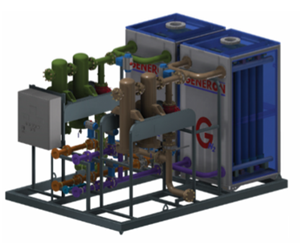
GENERON Family of Nitrogen Generators

GENERON is one of the world’s largest manufacturer of Membrane Nitrogen Generators.
Our patented GENERON® Membrane Separation Systems are engineered, designed, and manufactured to cover a wide range of flow capacities and operate more efficiently than other commercially available designs. We meet your space and design requirements; from our indoor and outdoor Cabinets, our Skid-Mounted designs, our Container and Mobile Packages, our Marine Series, or our Custom-Engineered-and-Built Systems.
GENERON maintains three manufacturing facilities that support the fabrication needs of our membrane nitrogen generation units. All process and nitrogen membranes are manufactured at the GENERON California Facility and system fabrication is accomplished in our facilities in Texas or China.
Why Choose GENERON® Nitrogen Generator Membrane Units:
- Extensive experience producing PSA and membrane units
- All the GENERON Group’s facilities are ISO 9001 Certified
- Modular design for easy installation
- Systems designed for long-term reliability
- Smallest physical footprint available
- Strategic alliance with dryer and compressor suppliers
- Extensive global service network
- GENERON Group has a top-rated membrane when comparing nitrogen/air ratio
Markets Served
- Food & Beverage
- Aerospace
- Automotive
- Pharmaceutical
- Chemical
- Oil & Gas
- Commercial
- Industrial
- & More
Applications
- Aircraft Fuel Tank Inerting
- Agriculture
- Liquid Sparging
- Autoclave
- Bacteria Elimination
- Blanketing
- Carbon Fiber Cutting
- Bio-fuels
- Fire Suppression
- & More
Membrane Nitrogen Generation Systems
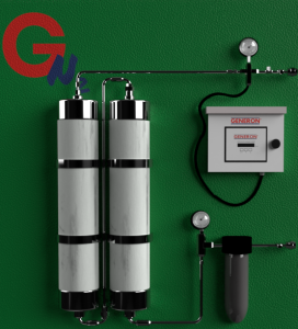
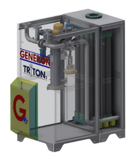
 NITROGEN ON WALL (NOW) System
- N₂ Capacity: 15 – 2,000 SCFH @ 100 – 175 psig
- Foot Print: 50” L x 8” W x 50” H
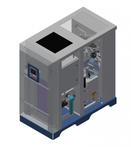
 GHPNS – HIGH-PRESSURE SYSTEM
with feed and booster compressor
- N₂ Capacity: up to 1,500 SCFH @ 500 – 5,000 psig
- Foot Print: 72” L x 36” W x 76” H
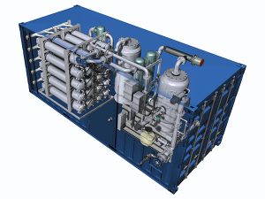
 CONTAINERIZED SYSTEM
with internal pre-treatment
- N₂ Capacity: 24,000 – 240,000 SCFH @ 200-500 psig
- Foot Print: 120”-480” L x 96” W x 102” H
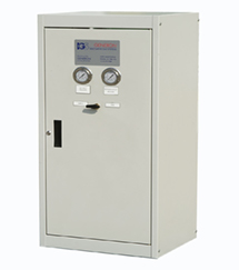
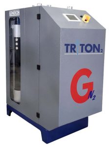
 6150 CP SERIES CABINET
with internal pre-treatment
- N₂ Capacity: 400-20,000 SCFH @ 100 – 175 psig
- Foot Print: 39” – 54” L x 25” W x 56” H
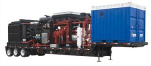
 Mobile Trailer Mounted System
- N₂ Capacity:30,000 – 90,000 SCFH @ 200 – 500 psig
- Foot Print: 240” – 480” L x 96” W x 102” H
 6800 CP SERIES CABINET
with internal pre-treatment
- N₂ Capacity: 4,000 – 60,000 SCFH @ 100 – 175 psig
- Foot Print: 84” L x 48” W x 101” H
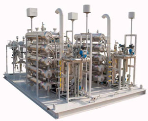
 CUSTOM SKIDDED SYSTEM
- N₂ Capacity: 1,500 – 110,000 SCFH @ 100 – 450 psig
- Foot Print: 120” – 480” L x 96” W x 102” H
 6800CP MODULAR SYSTEM
with external pre-treatment
- N₂ Capacity: 30,000 – 240,000 SCFH @ 100 – 175 psig
- Foot Print: 156” L x 55” – 110” W x 104” H
How does an Industrial Membrane Nitrogen Generator work?
The membrane separation of gases is simple in concept. At the heart of technology are polymeric membrane materials that allow for the rapid passage of one gas while minimizing the passage of another when applying pressure gradient across the membrane. The below figure demonstrates the relative rates of common gases, here with the focus on the separation of O2 from compressed air to provide a high purity N2 stream. GENERON® polymer has the best separation efficiency and lowest unit power consumption, i.e. the best properties for allowing the fast gases (H2O, H2, He, H2S, CO2, O2) to permeate the membrane relative to the slow gases (Ar, N2, CH4, C2+, SF6).
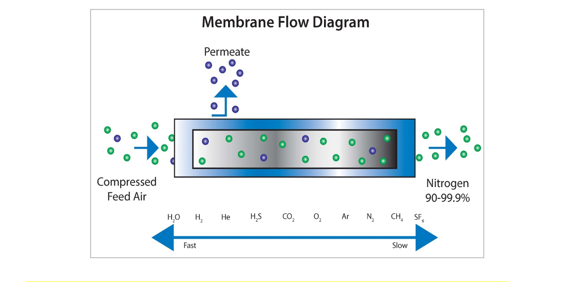
The GENERON® Membrane module contains over one million fibers that selectively remove oxygen and water vapor from compressed air, which enters one end of the membrane module. The enriched nitrogen product flows continuously from the other end of the module where it can be used in production, blanketing, or captured for storage.
GENERON® membranes combine the best available membrane materials with state-of-the-art fiber bundling and the optimum module fabrication methods to provide the most cost-effective solution for on-site gas separation production….and we have over 20 patents to prove it!
What does a N2 Generator look like in a system?
Typical System Configuration (PFD)
The process flow diagram below provides a basic system description of the Nitrogen Membrane Generator. A detailed P&ID will be provided for the exact project once all the system options have been established.
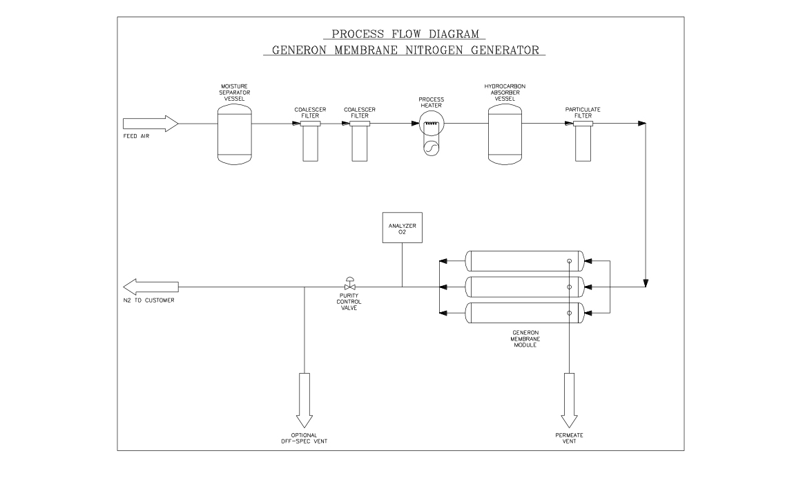
Compressed air is fed to an air receiver, which collects and removes the bulk of the oily condensate that is entrained the compressed air supply. The air receiver should be equipped with a condensate drain line, which automatically dumps excess fluid.
Compressed air is conditioned as part of the standard GENERON air pretreatment package by coarse and fine coalescing filters to remove virtually all of the remaining liquid water and oil still present in the feed air. The coalescing filters are each also equipped with a condensate drain line.
An optional process heater is provided which optimizes the membrane module performance by providing the membranes the optimum feed air temperature and superheats the air stream ensuring any residual water that is in the feed air stream is in a vapor phase.
After the Feed Air Heating step, the Feed Air is passed through another conditioning step. The Feed Air is passed through a bed of a specialized form of Activated Carbon. The Activated Carbon is utilized to remove from the Feed Air any Hydrocarbons that may be present in the air stream as a result of the compression process.
One final filtration step is undertaken to ensure that any of the activated carbon particles are captured prior to the GENERON Nitrogen Separation Modules.
The actual air separation process takes place in the GENERON Membrane Modules. The Nitrogen Membrane Modules are configured in parallel, so each module output adds proportionately to the capacity to the system.
The Separation is based on the principle of selective permeation, whereby each gas constituent has a characteristic permeation rate that is a function of its ability to dissolve and diffuse through a membrane. The module in which the nitrogen and oxygen separation takes place is a cylindrical bundle of hollow fiber membranes. Each bundle contains several million fibers, each about the size of a human hair. Pressurized air enters one end of the fibers and flows to the opposite end on the module through the fiber bores.
Gas separation takes place as the pressurized air contacts the membranes. “Fast” gases such as oxygen, carbon dioxide, and water vapor quickly permeate through the fiber walls and exit as an enriched gas at the vent port on the side of the module case.
Nitrogen, a slower gas, does not permeate through the fiber as quickly under flowing conditions. It flows down the bore of the fibers and exits at the product manifold at the end of the high-pressure shell.
The Process Control Valve is used to control the residence time of the feed air in the Membrane Modules. The Process Control Valve receives its control signal from the Oxygen Analyzer / PLC. The Control System utilizes a PLC with a PID control loop to maintain the desired compressed air residence time in the Nitrogen Module to achieve the Set Point Purity as determined by the Operator Panel and Oxygen Analyzer.
The GENERON Membrane System is equipped with purity assurance valves. The product valve allows on-spec Nitrogen product gas to flow into the customer’s pipeline. The product vent valve will vent off-spec product gas when the desired purity is out of range. An oxygen analyzer continuously monitors O2 content in the nitrogen product gas and would alert the operator and initiate the venting of off spec product if the product gas is outside predetermined set points established by the operator.
The GENERON Membrane System is optionally equipped with a standby mode that enables the system to go off line during periods of no demand. The system can be customized to operate on Customer selected pressure points that optimizes compressed air usage.

